
Turbochargers are almost universally used in medium and large bore road diesel engines in North America, and they are also almost fully popularized in small bore engines. The definition of a turbocharger is a centrifugal pump driven by exhaust gas, which can "recover" part of the waste heat from the engine cylinders. In specific racing engine applications, the rotational speed of a turbocharger may exceed 200,000 revolutions per minute, but in diesel engines, its maximum rotational speed is usually about 30% lower. The main function of a turbocharger is to provide pressurized intake air for the engine cylinders. In short, it increases the oxygen density in the intake air. In addition, the exhaust gas-driven turbine can also drive the reduction gear connected to the engine crankshaft through a fluid coupling. At this point, the turbocharger can assist in driving the crankshaft. This method is called turbo composite technology and is currently applied in the latest generation of Detroit diesel engines. It will be further introduced in the later part of this chapter. Figure 12-7 shows the right view of the 2010 Cummins ISX engine, on which the position of the turbocharger is marked.
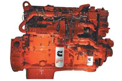
Figure 12-7 Right view of Cummins ISX Engine (marked with Turbocharger position)
Working principle
A turbocharger is an air pump driven by exhaust gas, consisting of a turbine and an impeller installed on the same shaft (see Figure 12-8). The shaft is suspended on the friction bearing by pressure lubricating oil (hydrodynamic suspension). The turbine impeller is driven by the energy (heat) of the engine exhaust gas and rotates within the turbine housing where the exhaust gas flows. The impeller is located in an independent compressor casing and acts on the air of the intake system, pumping it into the pressurized side of the intake system. The exhaust gas driving the turbine does not come into contact with the intake air acting on the impeller. Figure 12-9 shows the flow paths of gas and lubricating oil in a simple turbocharger.
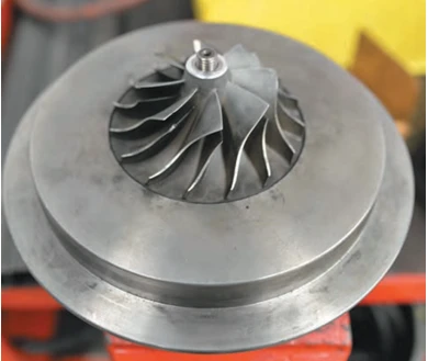
Figure 12-8 The impeller of the turbocharger (or compressor wheel)
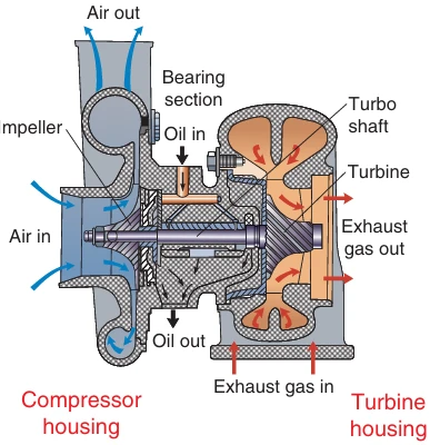
Figure 12-9 Cross-sectional view of the turbocharger (including the lubricating oil passage and gas flow direction)
The working principle of the compressor
The filtered intake air is drawn into the compressor casing and driven by the impeller on the turbine shaft compressor side. The turbine drives the impeller to rotate on the other side of the turbine shaft, so the actual rotational speed of the impeller depends on the working conditions inside the turbine housing. As the impeller rotates, the air in the intake system is accelerated to a high speed. High-speed airflow enters a diffuser radially outward. A diffuser is a throttling device, whose design objective is to convert the kinetic energy (motion energy) of the incoming air into pressure when the airflow passes through. The diffuser can be of the volute type (snail shape) or the blade type (see Figure 12-9). The efficiency of the blade diffuser is higher.
The working principle of the turbine
The exhaust gas is guided to the turbine housing. The greater the waste heat value of the engine (which usually increases with the increase of the engine output power), the higher the thermal energy of the exhaust gas. The exhaust gas radially enters the turbine housing and then enters through the volute (a snail-shaped structure with a gradually decreasing cross-section). The volute represents a form of throttling. But when the exhaust gas flows out of the volute, it expands and acts on the turbine blades, and then enters the exhaust system along the axial direction.
The extent to which the gas in the turbine housing expands depends on the heat of the exhaust gas. Under the high-output condition of the engine, the waste heat from the engine increases, and the effect of exhaust gas expansion on the turbine blades will raise the turbine speed. It should be emphasized that the rotational speed of a turbocharger mainly depends on the heat of the exhaust gas rather than its pressure. The significance of the volute should also be understood: the smaller the volute size, the stronger the throttling effect on the airflow, but a small-sized volute means that the exhaust gas expands more fully when it flows out. The best solution is to be able to control the flow area of the volute, which will be further discussed below. Figure 12-10 is a schematic diagram of the gas flow in a turbocharger, illustrating the key functions of the volute and diffuser: Please pay attention to the directions in which the gas flows into and out of the turbine housing and the compressor housing.
Airflow path
As shown in Figure 12-10, the airflow enters the turbine housing in a radial inflow and axial outflow manner. The air flows through the impeller housing in an axial direction and out radially. In the simplest turbocharger design, the intake passage or throat of the turbine housing is not segmented, that is, the exhaust ports of all cylinders lead to a single inlet channel. However, variable geometry turbochargers can regulate the airflow in and out of the turbine housing. This will be discussed later in this section.

Figure 12-10 Schematic diagram of the airflow principle of a turbocharger, demonstrating the functions of the volute and the diffuser.
Turbocharger type
First of all, it is important to distinguish between fixed-geometry turbochargers and variable-geometry turbochargers. This article defines it as follows:
• Fixed-geometry turbocharger: All exhaust gases flow through the turbine housing regardless of engine operating conditions.
• Variable geometry turbocharger: By external or internal control, the flow area inside the turbine housing is adjusted, or part of the exhaust gas is made to bypass the turbine housing.
As of 2001, the turbochargers used in most commercial diesel engines on highways still belonged to the fixed geometry type. But this situation has changed. Nowadays, when we see a fixed-geometry turbocharger on a truck diesel engine, it is usually a member of a series turbocharging pairing or part of a compound turbocharging system. At present, almost all turbochargers adopt some kind of technology to regulate (control) the flow of exhaust gas through the turbine housing, whether through an exhaust gas bypass valve or by using an internal variable geometry.
Fixed-geometry turbocharger
Let's first describe the working principle of the fixed-geometry turbocharger. Fixed-geometry turbochargers are designed to achieve optimal performance at specific speeds and specific waste heat loads, which means they are not very versatile. Engineers must select the operating time when the turbine efficiency is the highest. Most road engines that use fixed-geometry turbochargers typically achieve the highest efficiency of their turbines at full load and peak torque speeds. If the operating range is exceeded, the performance will decline. The fixed-geometry turbocharger has a simple structure. Figure 12-9 shows its typical structure.
Setting the peak turbine efficiency at the peak torque speed rather than the rated speed enables the fixed-geometry turbocharger to have self-regulating characteristics: when the engine speed increases, the actual time available for pressurizing and injecting fuel into the cylinder is shortened. If a fixed-geometry turbocharger is operated outside the specified speed range, the engine torque curve will drop rapidly, causing the engine to struggle at low speeds and high loads. When loaded at high speeds, the speed will drop rapidly, and fuel economy will also deteriorate.
Warning:
Improper matching of fixed-geometry turbochargers may lead to excessively high cylinder pressure, causing engine failure, or conversely, result in insufficient power, black smoke emissions and increased harmful emissions.
Technical tips:
Although truck diesel engines with fixed-geometry turbochargers are designed to achieve the highest gas efficiency at peak torque, most other diesel engines using fixed-geometry turbochargers (such as non-road heavy equipment or generator sets) typically achieve this at the rated speed (maximum power). In these applications, fixed-geometry turbochargers remain common and are typically optimized for full-power high-speed operating conditions.
Variable geometry turbocharger
The objective of the variable geometry turbocharger can be summarized as:
• When the engine load is low, make the turbine respond as quickly as a small turbocharger.
• When the engine load is high, make the turbine provide sufficient boost like a large turbocharger.
Modern turbochargers controlled by ECM can achieve all the above goals and precise regulation of all intermediate stages, thereby bringing faster response speeds (reducing turbo hysteresis) and lower emissions. Some current turbochargers also combine the use of external exhaust bypass valves and internal variable geometries to manage the boost pressure within the widest range of speeds and loads.
• Exhaust gas bypass valve control type
The exhaust gas bypass valve type turbocharger has been in use for many years. Its working principle is: through a "valve", all the exhaust gas is controlled to flow through the turbine housing, or part of the exhaust gas is directly bypassed to the exhaust system. At present, there are mainly two control methods:
• Pneumatic control: The operation of the bypass valve depends on the pressure of the intake manifold. Usually, a actuator tank with a spring is adopted. By default, the closed state allows the exhaust gas to flow entirely through the turbine. When the manifold boost pressure reaches the set value, the pressure overcomes the spring force to push the action rod, opening the valve to bypass part of the exhaust gas.
• Electronic control: Controlled by the engine ECM. For instance, some engines employ exhaust bypass turbines with dual intake ports. The ECM precisely manages the pressure acting on the actuator through solenoid valves and manifold pressure, achieving multi-stage boost regulation. Its control principle can be summarized as a compound control mechanism of "electronic - electric control - pneumatic".
• Volute controlled variable geometry turbine
Volute controlled variable geometry turbochargers have been widely adopted in today's diesel engines. Racing engines have been using variable aperture nozzles to control the flow area of the volute for many years, and diesel engines have borrowed this technology. The first volute controlled turbocharger applied to diesel engines emerged in the early 1990s, with limited initial success. But nowadays, the vast majority of diesel engine manufacturers have preferred to adopt variable volute technology rather than the traditional exhaust bypass valve turbocharger. For example, the variable Geometry turbine (VGT) installed on the Paccar MX13 engine shown in Figure 12-11 is a typical representative. To illustrate the working principle of the variable geometry turbine, we will take the typical volute control turbocharger shown in Figure 12-12 as an example for illustration.

Figure 12-11 Variable Geometry Turbine (VGT) Used on the Paccar MX13 engine

Figure 12-12 Sectional view of the variable geometry turbine (VGT), with a focus on its actuator
Variable nozzle turbocharger
Figure 12-12 shows a cross-sectional view of a typical variable nozzle turbocharger. Please refer to Figure 12-13 to identify the key components such as the turbine, pinion, nozzle blade and synchronous ring.

Figure 12-13 Working Principle of Components of VN turbochargers.
The variable nozzle turbocharger generates the required boost pressure by adjusting the blade Angle to change the volute flow area. This process is achieved by the oil pressure acting on the piston, which meshes with the CAM gear and the crank shaft, thereby driving the synchronous ring to rotate. The synchronous ring supports all the blade assemblies. Each blade is equipped with a helical groove. When the rotation position of the synchronous ring changes, the blade rotates with its pin shaft as the fulcrum, thereby achieving the synchronous adjustment of the blade's inclination Angle. Through this mechanism, the flow area of the volute (intake side) can be increased or decreased, which directly affects the gas efficiency inside the turbine housing. In short, the flow area of the volute determines the turbine speed and ultimately the boost pressure generated by the turbine compressor.
Variable nozzle control
The variable nozzle turbocharger is regulated by the variable nozzle control valve. This control valve is a proportional actuator managed by the engine control module, capable of converting the input current signal into a specific piston ring position. When the blades are close to the closed position (the blades will never be completely closed), the turbocharger generates the maximum boost pressure. The management of pressurized air is entirely dependent on the position of the blades, as the blade Angle directly determines the way the exhaust gas acts on the turbine. Figure 12-14 shows how oil pressure drives the piston ring to actuate the CAM and crank mechanism, causing the synchronous ring to rotate clockwise, thereby widening the blades and reducing the gas efficiency of the turbine.

Figure 12-14 VN Turbocharger: Increase the blade opening to reduce turbine efficiency.
When the oil pressure pushes the piston to move to the left (Figure 12-15), the synchronous ring rotates counterclockwise, adjusting the blades to an Angle close to the closed position, enhancing the turbine efficiency to provide maximum boost. This action process can be referred to in Figure 12-16.

Figure 12-15 VN Turbocharger: Reduce the blade opening to achieve maximum boost.

Figure 12-16 The role of the synchronous ring in controlling the blade opening.
The rotational speed of the variable nozzle turbocharger is fed back to the engine control module through an axial speed sensor based on the principle of an induction pulse generator. Its trigger signal is taken from the planar structure at a specific position on the turbine shaft.
3. Slip ring volute turbine
Another variable volute structure adopted by Cummins Honicell turbochargers: the flow area is adjusted by moving the slip ring through the VG actuator. Its goal is the same as that of Caterpillar's VN turbine, but the way it is achieved is slightly different. Figure 12-17 shows a typical VG actuator module used on engines after 2010.

Figure 12-17: VG actuator module used on a typical engine 10 years later.