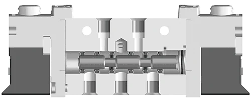
In pneumatic, hydraulic, and fluid control systems, solenoid valves are the core control components, widely used in industrial equipment, automated production lines, fluid transportation equipment, etc.
Many engineers and equipment maintenance personnel often fail to distinguish the differences between direct-acting, step-by-step direct-acting, and pilot-type solenoid valves when selecting them, which can lead to selection errors, equipment start-stop lag, coil burnout, excessive hydraulic shock, etc.
Based on national standards and mechanical industry standards, we will comprehensively analyze the working principle, advantages and disadvantages, and applicable scenarios of the three types of solenoid valves, and also explain the national standard graphic symbols of solenoid valves to help everyone solve the problems of solenoid valve selection and reading diagrams at one go!
Direct-acting solenoid valve
According to JB/T 7352-2026: The direct-acting solenoid valve directly drives the valve core to open and close by electromagnetic force, without a pilot valve structure, and supports zero-pressure start-up. The direct-acting solenoid valve has two types: normally closed and normally open. The normally closed type remains closed when the power is off. When the coil is energized, an electromagnetic force is generated, causing the moving iron core to overcome the spring force and attract the static iron core to directly open the valve, allowing the medium to flow through; when the coil is de-energized, the electromagnetic force disappears, the moving iron core is reset by the spring force and directly closes the valve port, preventing the medium from flowing. The structure is simple and the action is reliable, working normally under zero pressure and micro vacuum. The normally open type is the opposite.

Step-by-step direct-acting solenoid valve
According to JB/T 7352-2026: The step-by-step direct-acting solenoid valve is a composite structure of direct-acting and pilot-type, driven by electromagnetic force and acting on the main valve core to achieve opening and closing. It can operate under zero pressure. The step-by-step direct-acting solenoid valve is a combination of direct-acting and pilot-type principles. When there is no pressure difference between the inlet and outlet, after being energized, the electromagnetic force directly lifts the pilot valve and the main valve closing element one by one, opening the valve.

Pilot-type solenoid valve
According to JB/T 7352-2026: The pilot-type solenoid valve is driven by electromagnetic force to drive the pilot valve, using the pressure difference of the medium to push the main valve core to achieve opening and closing. It needs to meet the minimum working pressure difference to operate. The pilot-type solenoid valve is the most commonly used type, usually used in pipes with larger diameters and higher pressure. This type of valve has low power consumption, less heat generation, and the coil is less likely to burn out, allowing for long-term power-on and is energy-saving. Therefore, it is widely used. Compared with the pilot-type solenoid valve, although it is slightly more complex, it can achieve higher and more precise control effects, be able to control the opening and closing speed of the valve port, and have a good effect in reducing hydraulic shock. When the pilot-type solenoid valve is opened, there must be pilot pressure; otherwise, it cannot be opened. In the pressure range, the higher the medium pressure, the tighter the seal.
This solenoid valve is formed by the combination of the pilot valve and the main valve core; the normally closed type remains closed when the power is off. When the coil is energized, the magnetic force causes the moving iron core and the static iron core to attract each other, and the pilot valve port opens, allowing the medium to flow to the outlet. At this time, the pressure in the upper chamber of the main valve core decreases and is lower than the pressure on the inlet side, forming a pressure difference that overcomes the spring resistance and moves upward, achieving the purpose of opening the main valve port, allowing the medium to flow. When the coil is de-energized, the magnetic force disappears, the moving iron core is reset by the spring force and closes the pilot port. At this time, the medium flows into the balance hole, the pressure in the upper chamber of the main valve core increases, and is under the action of the spring force, moving downward to close the main valve port. The normally open type principle is the opposite.

How to choose between direct-acting and pilot-type solenoid valves?
Direct-acting solenoid valves are generally used for small diameters (the interface size of the ASCO8320 series is 1/8"-1/4") and low-pressure environments. This structure of the valve does not require the minimum pressure of the medium for opening, zero-pressure start-up, so compared with the start-up speed of the pilot-type solenoid valve, it will be faster, especially suitable for places requiring rapid cut-off. The power consumption of the pilot-type solenoid valve is greater, usually ranging from 5 to 20 watts. Frequent high-frequency energization can easily burn out the coil, but it is simple to control and has a wide range of applications.
The pilot-type solenoid valve is generally used in large-diameter and high-pressure scenarios. When this type of valve is opened, the minimum pressure required for the solenoid valve must not be lower than 0.05 MPa, and a pilot pressure is necessary; otherwise, it cannot be opened. In addition, the flow capacity of the pilot-type solenoid valve is larger than that of the direct-acting solenoid valve, and the general CV value can reach 3 or above. For compressed air purity requirements, the direct-acting type is not as strict. The electromagnetic head is small, the power consumption is low, 0.1-0.2 watts, and it can be frequently energized for long periods without burning out, and it is energy-saving. The upper limit of the fluid pressure range is higher, but it must meet the fluid pressure difference conditions. However, the impurities in the liquid are prone to block the pilot valve hole, and it is not suitable for using liquids with impurities.
• Pressure tolerance: In terms of the pressure tolerance of the two types, the pilot-type is greater than the direct-acting type.
• Response time: Compared with the direct-acting solenoid valve, the direct-acting solenoid valve has a faster startup speed. If it is used for rapid cutting, it is recommended to purchase the direct-acting solenoid valve. Because the pilot-type solenoid valve opens the small valve first and then the main valve, while the direct-acting solenoid valve directly opens the main valve.
• Flow capacity: The pilot-type is larger than the direct-acting solenoid valve. The general CV value can reach 3 or above, while the CV value of the direct-acting solenoid valve is generally less than 1. The direct-acting solenoid valve is activated by 0 pressure, while the pilot-type must have a pilot pressure, usually above 0.05 MPa.
• Power and consumption: The power of the direct-acting type is greater than that of the pilot-type.
• Media purity requirements: The pilot-type has a higher purity requirement for the flowing medium, but the direct-acting type is not so strict.
The meaning of the electromagnetic valve symbol
(According to GB/T 786.1-2021 "Fluid Transmission System and Components Graphic Symbols and Circuit Diagrams Part 1: Graphic Symbols") National standard information...
The electromagnetic valve graphic symbol consists of a square frame, an arrow, the symbol "T" for the plug, the drive/relief symbol, and interface letters. GB/T 786.1-2021 stipulates that the graphic symbol only expresses the valve function principle and does not represent the valve body shape or size. The meaning of the electromagnetic valve graphic symbol is generally as follows:
1. The square frame represents the working position of the valve. Each square represents a working position of the solenoid valve, that is, "position". The more squares there are, the more "positions" there are. For example, a two-position three-way valve represents two working positions. The "non-energized" and "energized" positions on the drawing are two different working positions.
2. Identify the normal position. GB/T 786.1-2021 stipulates: For a two-position spring-return valve, the square on the side close to the spring is the normal position (de-energized state); for a three-way valve, the middle square is the neutral position (normal position). When drawing the pneumatic or hydraulic system schematic diagram, the pipe should be connected to the interface corresponding to the normal position of the valve.
3. The arrow inside the square frame indicates that the two interfaces are in a connected state, and the direction of the arrow represents the flow direction of the medium.
4. The symbol "T" inside the square frame (plug) indicates that the path is cut off at this interface in this working position, and the medium does not flow.
5. The number of interfaces extending outside the square frame represents the "open" of the valve.
6. Interface letter identification (national standard general): The fluid inlet end is represented by the letter P, the outlet end by R (pneumatic)/T (hydraulic), and the working interface connecting to the actuator is represented by A, B, etc.
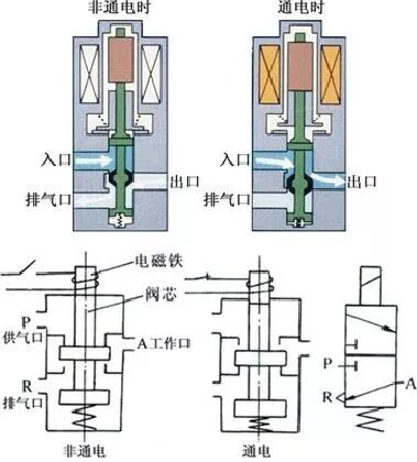
Example: A two-position three-way electromagnetic valve, two working positions, three pneumatic interfaces, are the inlet port (P), working outlet port (A), and exhaust port (R). When the solenoid valve is energized, P and A are open; when it returns to the normal position, R and A are open.

The following two pictures provide a detailed illustration of the entire working state of the valve: 1. The square within the yellow circle represents the interface connection state of the normal position of the electromagnetic valve (de-energized) (the spring side square, in accordance with GB/T 786.1-2021)

2. The square within the yellow circle represents the interface connection state of the energized (energized) position of the electromagnetic valve (the electromagnetic drive side square)

The working principle of the two-way three-way electromagnetic valve
The working principle of the two-way five-way electromagnetic valve